I²C VFD Display using Rust on an Arm Cortex MCU
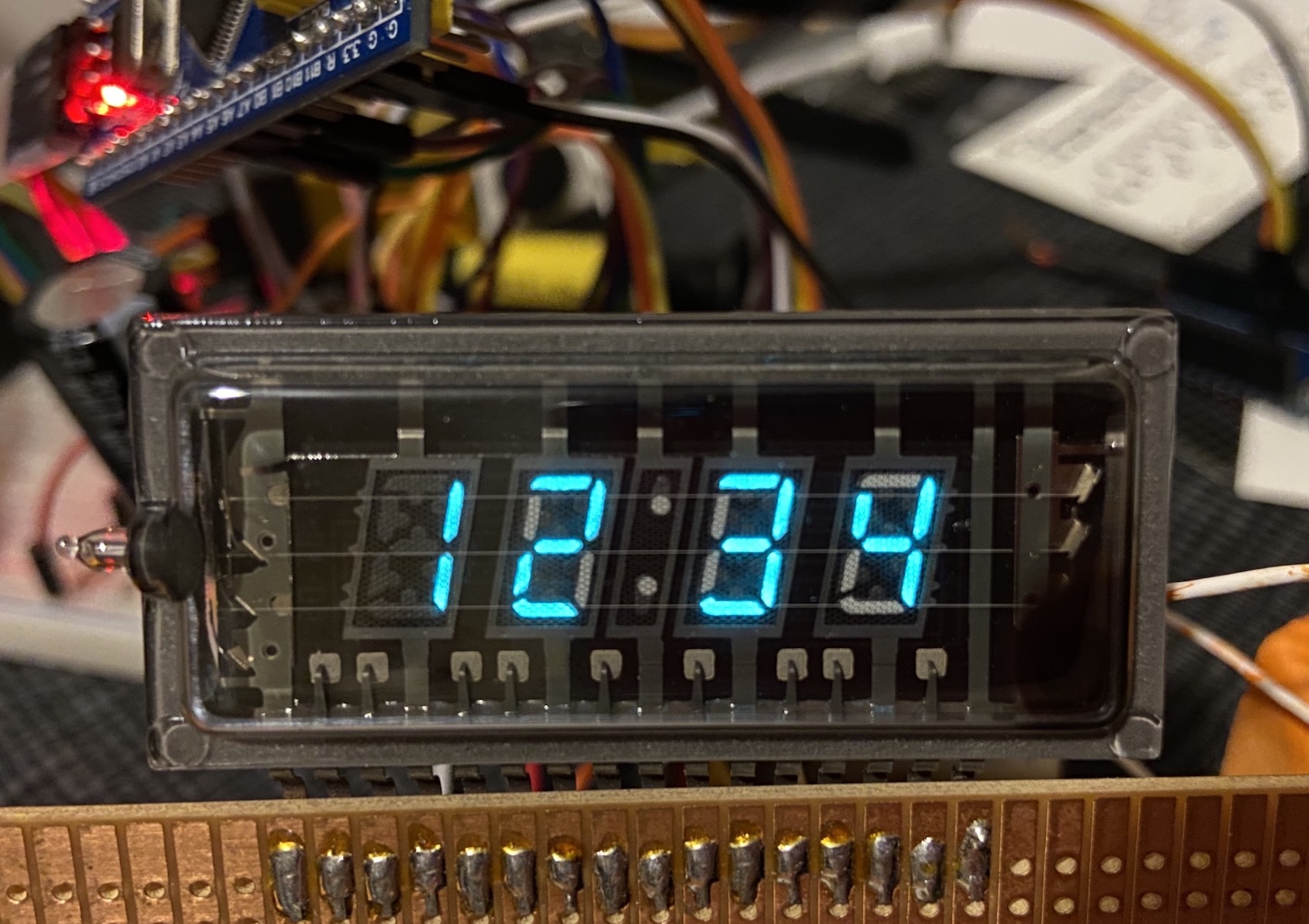
In the previous two blog posts we have built an LED bar display and a 7-segment LED display. We're taking a break from LEDs for our third display and basking in the blue-green glow of a Vacuum Fluorescent Display.
If you pull one out of an old microwave, VCR, or stereo you might not have a datasheet. Mine are from a junk box, and I was not able to find any documentation.
Michał Słomkowski has a great walkthrough detailing how to determine the pinout and power requirements of your VFD.
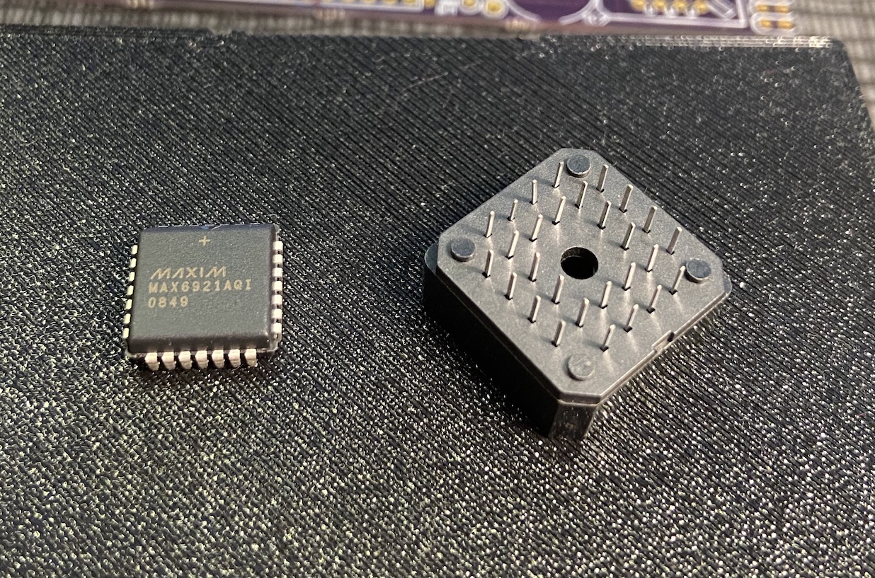
These displays require more power than our LEDs, and we're certainly not going to be able to hook this up directly to our microcontroller. One way to handle this is to use a dedicated VFD control chip such as the MAX6921.
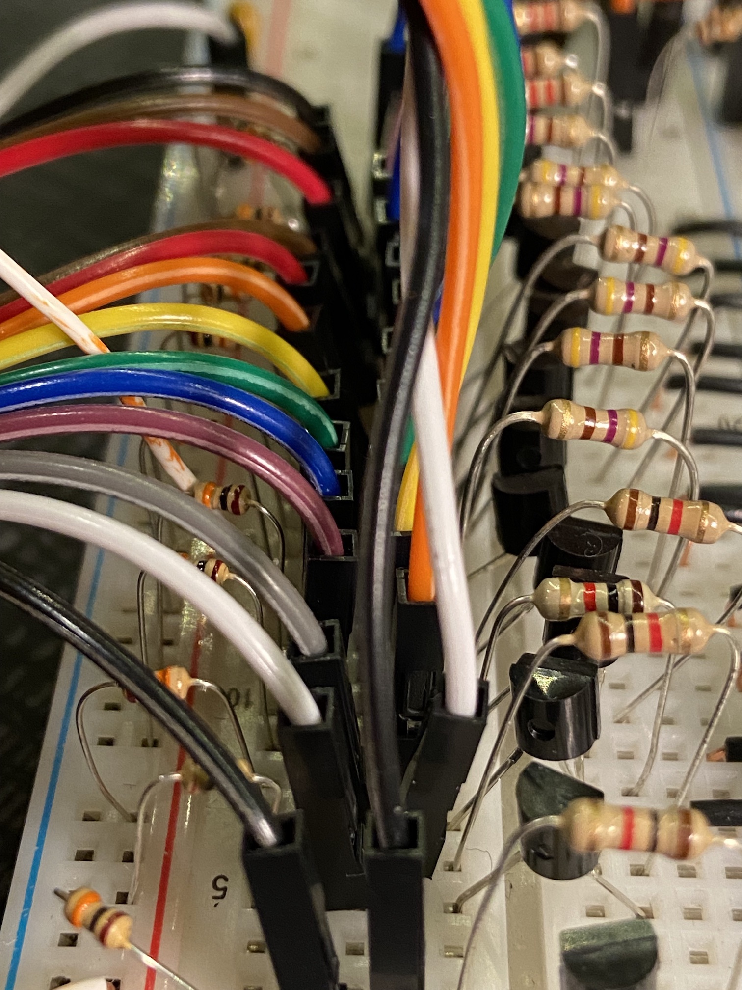
Instead, we are going to use a bunch more components and hook it up using transistors as switches. We'll hook the microcontroller up to the base of the transistors which will turn on a higher voltage path powering the display.
Oops, All Anodes
Unlike our LEDs, each of the segments of the VFD is an anode. The grids that turn each digit on and off are also anodes.
There are a few different ways to hook it up. This is what I decided on.
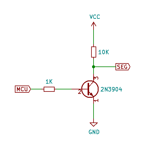
You can use a general purpose BJT or MOSFET here. I used 2N3904 transistors because I had a bunch of them, and I also used some 2N2222s because I like how many 2s are in the name. It's the weekend, we don't need to justify ourselves.
We'll need one of these for each segment and each grid pin.
We can see that with this configuration the display will default to being powered. When the transistor is on, the segment or grid will be pulled low. This means our MCU outputs will be active-low.
What about the cathode? VFDs, like other vacuum tubes, have hot filaments running across the grids. This is the cathode. We'll keep it steadily powered. I have not tried it, but these displays should run more evenly if you drive the filament with alternating current. We will get away with DC here but if you have an appropriate transformer or some other source of AC, it would be worth experimenting.
In my case, the anodes require 8.2V, and I ended up needing 0.8V across the filament. I used a 12V power supply with an adjustable buck converter for a high voltage rail for the segments and grids. I then added a 3V regulator to set up another power rail for the MCU and the filament. I added a resistor plus a little slider pot to trim down the filament until it was just below the point where it would glow red.
Software
This particular display really wants to be a clock, so we will need to adapt our code on the host to handle the fact that the most significant digit only goes up to 1. We also have the colon segment which I didn't need, so I just left it off.
On the firmware side, we have pretty much everything we need already built for the previous displays. The only real changes needed are to alter the segments to be active low and start out in the HIGH state. You can find the code here.