Rust I²C Bubble Display
In the previous post we looked at a simple LED bar display. This time we have a tiny 7-segment bubble display.
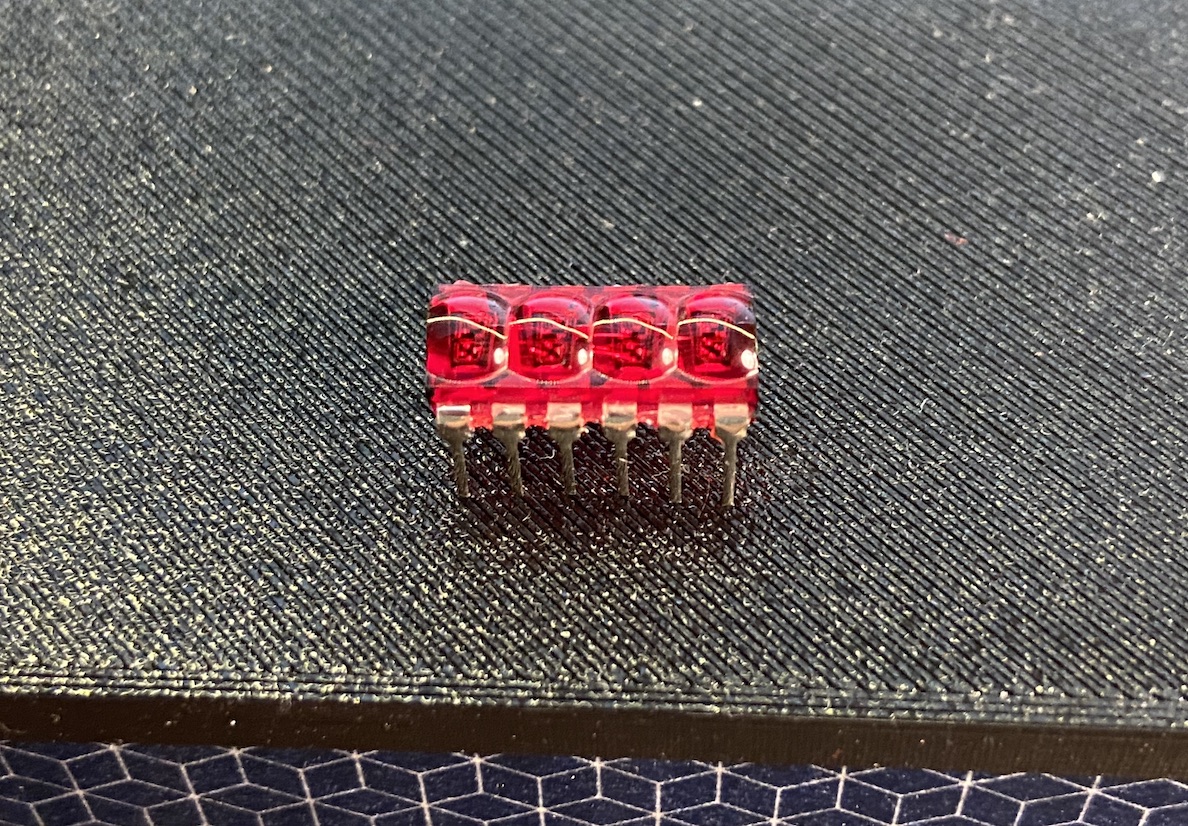
Let's first decide how we're hooking this up. To reduce the number of pins, displays like these are usually wired internally so that all the segments for each of the digits are connected together. Additionally, either the anodes or the cathodes of the LEDs for each digit are connected together. In this case, we have a common cathode display. This means we can only turn a single set of segments on at a time, effectively, we can only send one number to the display at a time. If it's an 8 for example we turn them all on, if it's 9, one fewer. To work around this, we need to multiplex the display. We'll turn off all digits but the first while sending the segments for the first position, turn all but the second digit off while sending the segments for the second digit, and so on. We'll do this fast enough for nobody to notice.
We also need to consider power constraints. If we hook the segment pins directly (via current limiting resistors) to output pins supplying 3.3v, and the digit pins directly to open drain pins, the worst case, with 7 segments and the decimal point turned on, we'll get all 8 feeding into a single pin. I hooked up an ammeter, 3.3v, experimented with current-limiting resistors to get the brightness I was happy with and measured about 14mA. Our pins can sink about 20mA, so we'll be in spec. See the third display, for what to do when you're over the power budget and this is not an option.
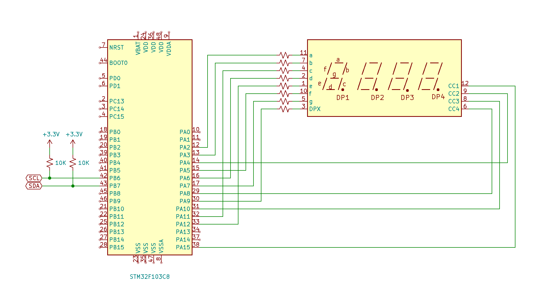
This is how I connected mine. I chose those pins so that I could add a circuit board with minimal wiring that snapped onto the microcontroller board with pin headers. Your constraints might be different.
Note also that you can get chips that do most of this for you. Two popular chips in the hobbyist community are the MAX7219 and TM1637.
Let's look at the code. You can see the complete code for the displays in the repo. Much of it is the same as the previous display, so check that for an explanation.
We're going to use a couple new features for our IO pins. We turn on our digits by switching from high-impedance state to ground, a digital low signal. Our segment pins on the other hand, we turn on with a logic high value. It would be nice to consider the electrical reality only at setup time and once that is done, put it aside and deal more directly with the logical state of our display. You’ll see a similar idea when datasheets talk about “asserting” a pin. A signal may be active high, or active low. Asserting the signal is setting the active state.
The OutputSwitch trait is what we want here.
// Digit pins are defined like this
    pins_a
        .pa8
        .into_open_drain_output_with_state(&mut pins_a.crh, State::High)
        .downgrade()
        .into_active_low_switch(), // ones
// Segment pins are defined like this
    pins_a
        .pa7
        .into_push_pull_output_with_state(&mut pins_a.crl, State::Low)
        .downgrade()
        .into_active_high_switch(), // g
We're calling into_active_low_switch() or into_active_high_switch() which returns a Switch type, so we can define our Display like so
pub struct Display {
    digits: [Switch<Pxx<Output<OpenDrain>>, ActiveLow>; 4],
    segments: [Switch<Pxx<Output<PushPull>>, ActiveHigh>; 8],
}
This allows us to use the more natural digit.on() and digit.off(). The other thing you'll notice is that output_with_state lets us define the initial state of the pin right up front.
There's one snag with the IO pins. To make wiring easier, we want to use PA15 which is by default used for JTAG. Since JTAG is often used for debugging, it's on by default. We are debugging over SWD, so we can disable JTAG to use PA15 as a general purpose pin. Since we're using the HAL, rather than our device just glitching or failing, the compiler will remind us if we try to use a pin that is set up incorrectly.
Here's how we remap the pin.
let mut afio = device.AFIO.constrain(&mut rcc.apb2);
let (pa15, _, _) = MAPR::disable_jtag(&mut afio.mapr, pins_a.pa15, pins_b.pb3, pins_b.pb4);
We give disable_jtag the pin we got from spliting gpioa, and it returns us a nice shiny generic pin, we can use like the others.
Driving the display
The most important new thing we will need is a timer to continually refresh the display. This means we'll want a new RTIC task. We'll set up TIM1, a generic timer to invoke our interrupt at a particular refresh rate.
let mut refresh_timer =
    Timer::tim1(device.TIM1, &clocks, &mut rcc.apb2).start_count_down(280.hz());
refresh_timer.listen(Event::Update);
We'll display a single digit of our display on each invocation of the interrupt, so four invocations will be a full cycle. We'll want at least 4 × 60hz, but 60hz is a bit annoying if you're moving your head, so let's go with 4 × 70hz, so 280hz. You can slow that right down to a few hertz to see exactly what is going on when you're debugging.
The function to select the digit to turn on looks like this:
fn select_digit(display: &mut Display, digit_position: usize) {
    let digit_select = 1 << digit_position;
    for (i, digit) in display.digits.iter_mut().enumerate() {
        if (digit_select >> i) > 0 {
            digit.on().unwrap();
        } else {
            digit.off().unwrap();
        }
    }
}
We're making use of on() and off() from switch_hal that I mentioned, to make this a little more readable.
Here's our new set of shared resources:
struct Resources {
    i2c: I2C1,
    display: Display,
    refresh_timer: CountDownTimer<TIM1>,
    #[init([0,0,0,0])]
    display_buffer: [u8; MESSAGE_LENGTH],
}
The i2c event task will fill the display buffer, which will be shared with our display task.
#[task(binds = I2C1_EV, resources = [i2c, display_buffer], priority = 2)]

#[task(binds = TIM1_UP, resources = [refresh_timer, display, display_buffer], priority = 1)]
The i2c device, the display and the refresh_timer are initialized by init and only used in one task each, so we don't need to worry about synchronization. The data we want to display will be shared in display_buffer. We want to read our incoming data right away, so we'll give the I²C task a higher priority than our display refresh timer. Since our display_buffer is shared between tasks with two different priorities, in the lower priority task, where we can be preempted, RTIC will give us a mutex proxy object we can use to access the resource. We'll ignore the fact that in this very particular case, our 4 bytes of data should be in a single, aligned machine word, so our access should be atomic anyway. This code will continue to work if we were to add a byte to our buffer.
In the highest priority task this resource appears in, our I²C events task, we can write to the buffer directly, since we won't be preempted.
Here's the complete task:
#[task(binds = TIM1_UP, resources = [refresh_timer, display, display_buffer], priority = 1)]
fn tim1_up(c: tim1_up::Context) {
    static mut DISPLAY_DIGIT: usize = 0;
    let mut display = c.resources.display;
    let mut display_buffer = c.resources.display_buffer;

    let mut frame: u8 = 0;
    display_buffer.lock(|buf| {
        frame = buf[*DISPLAY_DIGIT];
    });
    select_digit(&mut display, *DISPLAY_DIGIT);
    output_segments(&mut display, frame);

    *DISPLAY_DIGIT += 1;
    if *DISPLAY_DIGIT >= MESSAGE_LENGTH {
        *DISPLAY_DIGIT = 0;
    }
    c.resources.refresh_timer.clear_update_interrupt_flag();
}
We're keeping track of which digit we are displaying in a static mut variable which will persist across interrupt invocations. Each time we hit the interrupt, we grab a byte for a single digit, turn on that digit in the display, output the segments, and increment the digit for the next pass. Here we might also want to do some data transformation. For my purposes, I wanted to do the conversion on the host system, so we're just dumping the bits to the segments. They are arranged as standard 7-segment display a–f plus the decimal point, but that is not a particularly useful mapping. You could create a kind of "font" table mapping numbers to segments for numerals. It might be nice for the first byte sent from the host to specify decimal, hexadecimal, or raw mode. One tip if you do this, you might consider up-front how you want to handle the difference between displaying a zero and no value at all.
Getting the message
RTIC and the Rust compiler will help us keep track of where we need mutually exclusive access to a resource, but it's up to us to make sure that we keep everything logically consistent for our application. For example, we could update our buffer after each byte received from our host, after all, it's going to be fast enough, and it won't really matter if we're displaying half of one value and half of another for a split second. (I am chuckling to myself that I'm getting into screen tearing when talking about a 7 segment LED display.) Worse though, might be if communication is interrupted, or the host just sends an incomplete message. So let's not send the message to the display until we get a complete payload from the host.
We'll clear at the beginning of the transaction.
if sr1.addr().bit_is_set() {
    *READ_COUNT = 0;
    *PAYLOAD = [0; MESSAGE_LENGTH];
    i2c.sr1.read();
    i2c.sr2.read();
}
We'll ignore extra bytes if the host sends too many.
if sr1.rx_ne().bit_is_set() {
    let rx = i2c.dr.read();
    if *READ_COUNT < MESSAGE_LENGTH {
        PAYLOAD[*READ_COUNT] = rx.bits() as u8;
    }
    *READ_COUNT += 1;
}
We'll write to the buffer at the end of the message.
if sr1.stopf().bit_is_set() {
    if *READ_COUNT > 0 {
        *display_buffer = *PAYLOAD;
    }
    i2c.sr1.read();
    i2c.cr1.modify(|_, w| {
        w.ack().set_bit();
        w.stop().clear_bit()
    });
}
Using the display
Let's try hooking up our display. Let's hook it up to an Arduino again, but this time we'll send random bytes for that alien microprocessor look.
#include <Wire.h>

void setup() {
  randomSeed(analogRead(0));
  Wire.begin();
}

byte randNumber;

void loop() {
  Wire.beginTransmission(0x34);
  for (int i = 0; i < 4; i++) {
    randNumber = random(256);
    Wire.write(randNumber);
  }
  Wire.endTransmission();
  delay(20);
}
Great, now let's try hooking up to the Raspberry Pi. You can check the pinout here. It looks like we need pins 1(3V),3(SDA - Data),5(SCL - Clock), and 6(Ground).
Let's run i2cdetect from the i2ctools package
pi@koroks:~ $ i2cdetect -y 1
     0  1  2  3  4  5  6  7  8  9  a  b  c  d  e  f
00:          -- -- -- -- -- -- -- -- -- -- -- -- --
10: -- -- -- -- -- -- -- -- -- -- -- -- -- -- -- --
20: -- -- -- -- -- -- -- -- -- -- -- -- -- -- -- --
30: -- -- -- -- -- -- -- -- -- -- -- -- -- -- -- --
40: -- -- -- -- -- -- -- -- -- -- -- -- -- -- -- --
50: -- -- -- -- -- -- -- -- -- -- -- -- -- -- -- --
60: -- -- -- -- -- -- -- -- -- -- -- -- -- -- -- --
70: -- -- -- -- -- -- -- --
We don't show up, that's no fun.
We don't show up because while we do respond with the ACK signal when we match our address, and when we receive a byte, we are currently not doing anything when the master device asks us to reply. Linux mainly deals with SMBus devices. SMBus is a flavour of I²C with a few extra rules and expectations. I²C scanners usually send a test byte and request that we transmit.
To handle this, all we need to do is reply when transmit is expected (TX_E), and the byte transfer is not finished (BTF).
if sr1.tx_e().bit_is_set() && sr1.btf().bit_is_clear() {
    i2c.dr.write(|w| w.dr().bits(4));
}
Let's reply with 4. 4 is a good number.
pi@koroks:~ $ i2cdetect -y 1
     0  1  2  3  4  5  6  7  8  9  a  b  c  d  e  f
00:          -- -- -- -- -- -- -- -- -- -- -- -- --
10: -- -- -- -- -- -- -- -- -- -- -- -- -- -- -- --
20: -- -- -- -- -- -- -- -- -- -- -- -- -- -- -- --
30: -- -- -- -- 34 -- -- -- -- -- -- -- -- -- -- --
40: -- -- -- -- -- -- -- -- -- -- -- -- -- -- -- --
50: -- -- -- -- -- -- -- -- -- -- -- -- -- -- -- --
60: -- -- -- -- -- -- -- -- -- -- -- -- -- -- -- --
70: -- -- -- -- -- -- -- --
Now we show up!
Now we can use the standard tools to talk to our display. As an example, let's use i2cset. We need to tell it to use i2c device 1, set our address 0x34, and give it 4 bytes of data corresponding to the raw segments we want to turn on.
pi@koroks:~ $ i2cset -y 1 0x34 0x5B 0x6d 0x63 0x39 i

Koroks courtesy of my 11-year-old. Ferris The Squishable Rustacean by E. Dunham