Making Custom I²C Displays
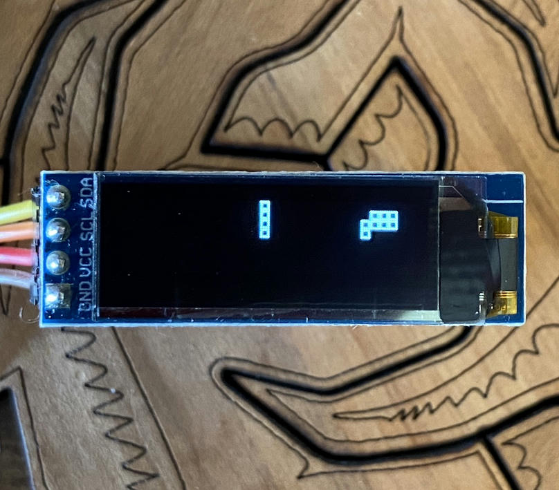
If you want to add a small display to your microcontroller project, there are a number of options available. One of my favourite inexpensive and easily available options are these tiny OLED displays.
You can also find 7-Segment LED displays, LED matrix displays and LCDs. These often use the I²C interface, which is handy because you only need to use two data pins to talk to them. I²C is pretty ubiquitous, so you'll be able to hook them up to pretty much any microcontroller or computer you're likely to encounter. Additionally, since I²C is a shared bus, you can even chain multiple displays and sensors together.
So how do they work? These devices have their own embedded microcontrollers. They're hidden everywhere these days.
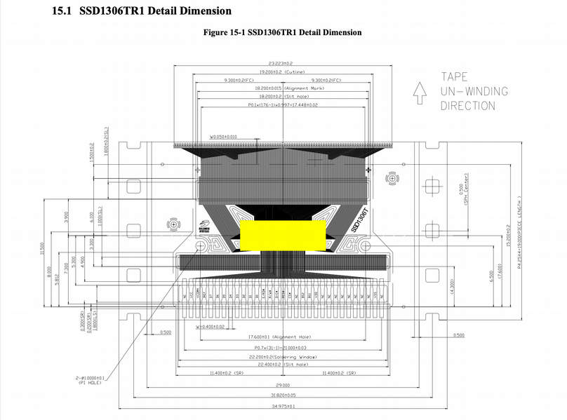
Incidentally, if you're wondering where the chip is on these little SSD1306 OLED displays it's not immediately apparent. The circuit board contains some support components, but no chip. The answer is it's embedded in the flex cable connected to the screen itself. It's the yellow box in the image below.
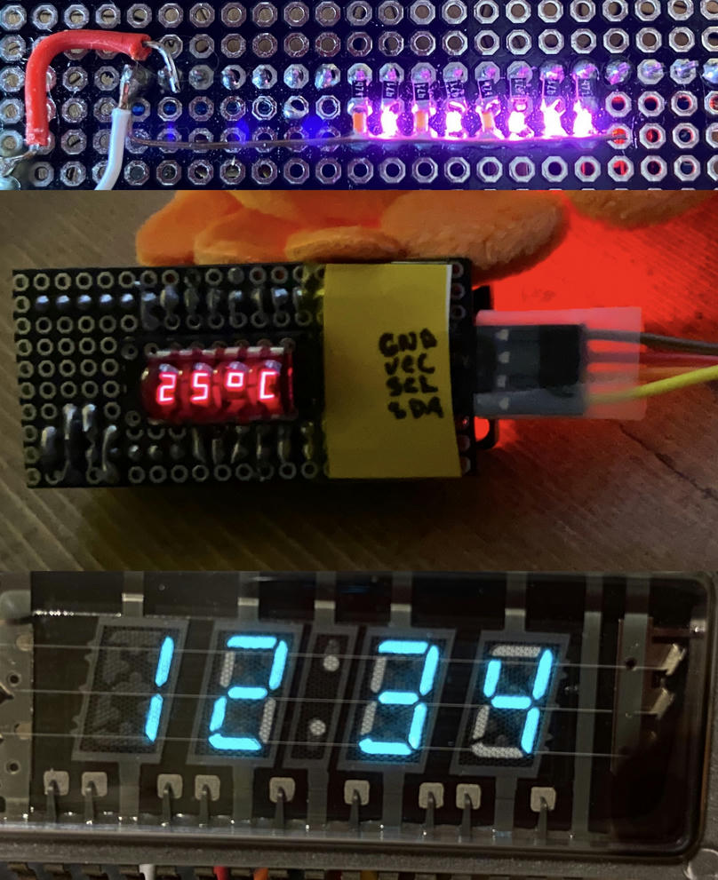
I wanted something a little different from what is commercially available, so I built my own. I'll walk through how I went about making three different displays. The first is an array of pink LEDs. This could be used to indicate status or activity or used as a bar graph. For the second one I just had to use one of these awesome little 7-segment LED bubble displays. You might recognize the vintage calculator look. For the love of the blue-green glow, the third display is a VFD, a Vacuum Fluorescent Display.
Please let me know on Twitter @NeedTungsten if this helps you build your own display, I'd love to see it!
This was also an opportunity for me to learn about embedded development using Rust and provide a detailed example of a project that is a little more than blinking a few leds—though we'll certainly blink a few here. If you don't care so much about the details of the implementation feel free to skip the Rust stuff and check out the git repository. You can flash the code and use the device with an Arduino, a Raspberry Pi, Circuit Python, Linux or whatever you want as the host.
I have a number of these ARM Cortex-M "Blue-Pill" clone boards, and frankly, they're not great. If I can press them into service as permanent display modules, to use them up, that will suit me fine.
To get our bearings with the hardware, the software, and the communication protocol, let's start with a simple array of 8 LEDs.
Development Environment
If you have not already done so, you might want to start out with a simple LED blinky project to make sure you have all your tools set up correctly. Here are some resources to get started:
You can compile this first example with cargo build --release --bin i2c-leds and flash it to the device with cargo flash --release --bin i2c-leds --chip STM32F103C8. For debug output cargo embed --release --bin i2c-leds --chip STM32F103C8
LED Bar Display
Let's walk through the code first, and I'll talk about the hardware as we go.
#![no_main]
#![no_std]

// ...

#[panic_handler]
fn panic(info: &PanicInfo) -> ! {
  rprintln!("{}", info);
  loop {}
}
We declare no_std so we don't pull in the parts of the Rust Standard Library for things like multithreading and file I/O that require an underlying Operating System.
no_main lets us declare our own entry point. The reset vector of the microcontroller will be set up to jump to our main entrypoint after doing a few things like initializing the RAM.
Similar to our main entrypoint, we need to declare a panic handler. There are a number of options here, depending on your method of debugging. You can use a simple panic-halt and add a breakpoint. Or panic-itm or panic_semihosting. I've been using rtt for flashing and logging, so I defined my own panic handler to print to output to the same channel. probe-rs is pretty great, well worth checking out.
Concurrency
It's not so critical for this first simple display with 8 leds, but for the other two displays at least, we'll need to handle two tasks simultaneously. We'll be receiving data from the host and at the same time multiplexing digits to drive the display.
The way I²C works is the host system generates the clock signal and sends requests on the shared bus. The slave device, which is what we are implementing, listens for its address and sends acknowledgement pulses after reading data from the bus. The master receives these ACKs and knows it can move on to the next request. If we are busy updating our display when the data is ready, we are not going to be efficiently servicing the bus. The protocol does actually provide for this, if we don't send the ACK right away, the clock is held until we do. This is known as clock stretching.
We can't always rely on this! One problem I ran into when testing on the Raspberry Pi, was a buggy clock stretching implementation (in the Broadcom chip). It looks like instead of correctly stretching the clock, they instead mask it. This causes glitches since when the clock signal is unmasked you'll often get a partial unaccounted for clock pulse which throws everything out of sync. Read the details here. (This is not the only I²C issue I've come across. It's not even the only clock stretching issue, see here for another issue with the ESP8266.)
Even without these bugs though, that's no way to live! Our system is plenty fast enough to get the bits off the wire. The way to do this efficiently is by using interrupts. The STM32F103 provides a hardware I²C interface that handles the clock and data for us. Data pulses are received serially on the SDA pin and accumulate in a shift register. Once the register is full, the system fires an interrupt. At this time we need to read the data and clear flags to acknowledge various conditions.
Just like in multithreaded code, we're going to need to manage shared access to resources across concurrent execution contexts. There's some interesting experimentation going on right now in the embedded Rust community right now. therealprof has a good comparison of resource sharing implementations that's well worth checking out.
Again, for this simplest display, there's not much concurrency, we're doing setup and then we're either servicing the interrupt or idling. We are, however, using the same framework for all three displays, so let's take a look at the code.
For this project, I chose to use RTIC.
#[rtic::app(device = stm32f1xx_hal::stm32, peripherals = true)]
const APP: () = {
    struct Resources {
        i2c: I2C1,
        leds: [Pxx<Output<PushPull>>; 8],
    }
    #[init]
    fn init(c: init::Context) -> init::LateResources {

        // Here we set up the device, and initialize `i2c` and `leds`

        rtic::pend(Interrupt::I2C1_EV);
        init::LateResources { i2c, leds }
    }

    #[idle]
    fn idle(_: idle::Context) -> ! {
        loop {}
    }

    #[task(binds = I2C1_EV, resources = [i2c, leds], priority = 2)]
    fn i2c1_ev(c: i2c1_ev::Context) {
        let i2c = c.resources.i2c;
        let leds = c.resources.leds;

        // Here we read i2c data and output to leds
    }
};
We declare our shared resources at the top of our APP pseudomodule, in this case our i2c interface and our array of LEDs. RTIC calls our init function with a context, providing access to the device peripherals, we do setup and return LateResources. RTIC provides tools to safely access these shared resources in tasks, including interrupts. Crucially, all interrupts are disabled until after the initialization of Resources so we can be certain they will be valid inside our interrupt handler.
I'll have more to say about RTIC later.
rtic::pend(Interrupt::I2C1_EV) is a convenience function for setting the interrupt vector. If you're not using RTIC you'll want to nest your vectors directly using cortex_m::peripheral::NVIC::unmask(Interrupt::I2C1_EV);. This sets the entrypoint for our I2C1_EV task. We'll jump to this task any time the I²C hardware peripheral has an event we need to handle. Because this task is the highest priority and can't be preempted, and because tasks are not re-entrant, and because our processor is single core, inside this task we can access our shared resources without a critical section or any other locking.
Device Initialization
let device: stm32f1xx_hal::stm32::Peripherals = c.device;
let mut rcc = device.RCC.constrain();
let mut flash = device.FLASH.constrain();

let _clocks = rcc
    .cfgr
    .use_hse(8.mhz())
    .hclk(24.mhz())
    .sysclk(24.mhz())
    .pclk1(12.mhz())
    .pclk2(12.mhz())
    .freeze(&mut flash.acr);
Here we take ownership over the device peripherals. Peripherals is a singleton with mostly zero sized types only used at compile time to let us know when we have done something inconsistent.
RCC is Reset and Clock Control. We'll use the RCC builder to configure our clock tree. As you can imagine, the timing of the system components is interdependent, so we configure it all at once and freeze that configuration. hse is the external oscillator that we have already determined is 8Mhz. The bus and system clock hclk and sysclk we'll set to the same speed at a multiple of our external clock source. We'll be using the I2C1 interface and, checking the reference manual, it's part of APB1, so we'll need to be sure to enable clock PCLK1 to make sure it's powered on. Reading the manual you'll also see references to registers such as RCC_APB1ENR. We won't need to write to these directly, the HAL is looking after configuring these using the code above. I recommend setting up your IDE to let you click directly into the supporting crates, so you can see for yourself whenever you're curious.
Speaking of curiosity, it's easy to get the system into an unresponsive state where it won't accept requests to flash new code to the device. A great way to do this is to misconfigure the clock! It is not bricked, here's how to fix it. You should have either a jumper, or a button labelled boot0. For normal operation this signal is tied low. When pulled high, rather than running user-flashed code, the system will run the bootloader code. Since we are flashing via the debug port, and not USB, we're not too concerned about what this code is doing, the important property for us is that it's configured correctly and will allow us to flash a corrected version of our code. So the procedure if you run into this problem is to set the Boot0 jumper to high (or hold down the button) while resetting the system. At this point the bootloader will be running, and we can re-flash the device. Next we'll need to move the jumper back to low and reset again to switch back to our code. (Oh wow, I just had a flashback to a part-time tech-support job I had in university)
So that's: reset with boot0 high, flash, reset with boot0 low.
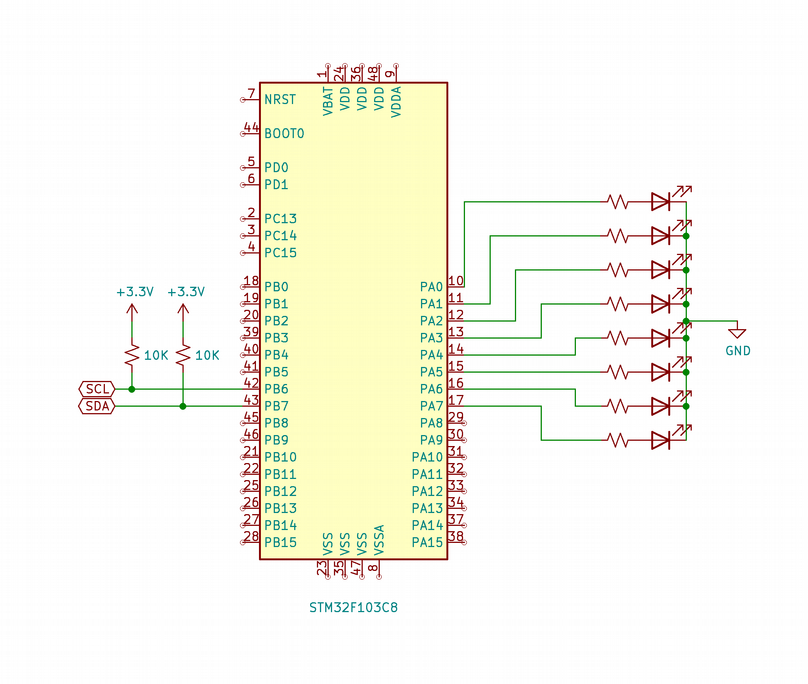
Ignoring all the support circuitry on the blue pill development board, here's a schematic for what we need to add. The resistors will depend on your LEDs, their color and how bright you want them to be. I used 470Ω, but they are a little bright for my liking. Something larger would be better
Let's set up our I/O accordingly
let mut gpioa = device.GPIOA.split(&mut rcc.apb2);
let leds = [
    gpioa.pa0.into_push_pull_output(&mut gpioa.crl).downgrade(),
    gpioa.pa1.into_push_pull_output(&mut gpioa.crl).downgrade(),
    gpioa.pa2.into_push_pull_output(&mut gpioa.crl).downgrade(),
    gpioa.pa3.into_push_pull_output(&mut gpioa.crl).downgrade(),
    gpioa.pa4.into_push_pull_output(&mut gpioa.crl).downgrade(),
    gpioa.pa5.into_push_pull_output(&mut gpioa.crl).downgrade(),
    gpioa.pa6.into_push_pull_output(&mut gpioa.crl).downgrade(),
    gpioa.pa7.into_push_pull_output(&mut gpioa.crl).downgrade(),
];
Our leds are all on pins connected to the same general purpose I/O port, GPIOA. This means they are all controlled by a single register. For this particular display, we could set all of our LEDs at once with a single write, and maybe I'll try that later. Most of the time that's not the best option. Most of the time we want to control each pin individually, hence the split() function above, that returns a structure that gives us access to the individual pins.
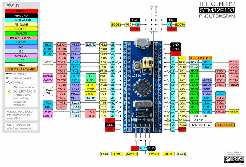
As you can see from the datasheet, or from this nice colorful pinout diagram most of the pins have more than one possible function.
Since the pins on the device have multiple functions, the types of our pin references reflect that. In the code above we set our LED pins to push pull output and then call downgrade() which erases the specific type and gives us a Pxx generic output pin that we can put into an array.
let mut gpiob = device.GPIOB.split(&mut rcc.apb2);
let _scl = gpiob.pb6.into_alternate_open_drain(&mut gpiob.crl);
let _sda = gpiob.pb7.into_alternate_open_drain(&mut gpiob.crl);
We're using the first I²C interface I2C1, so we'll need to use pins PB6 and PB7. PB6 will be the clock signal, and PB7 will be the data. If you think about it, because of clock stretching, we're also letting some data, data about back pressure, sneak into the clock signal.
We set these pins to their alternate function to tell the system to route the signal to the I²C interface. This also sets the pins to open drain. Since this is a shared bus, each device needs a way of sending signals that any of the others can detect. The way this works is we power the bus via the pullup resistors, ths provides the high signal. In out case, see the 10K resistors on the schematic. The open drain setting means that any device can sink current, pulling the signal low when it's their turn to send. Our LEDs are set to push-pull meaning we drive current through the LEDs to turn them on, in the case of our I²C pins, we generate a signal pulse by pulling the pin low.
You may have pullup resistors or spaces for them on the device you want to connect to, for example, this Arduino Pro Mini has a footprint for adding some SMT pullups Sparkfun Arduino Pro Nano. You may be ok having multiple pullups on the bus, but be aware that you will have to consider your resistors as being in parallel.
You'll notice that this is the only place we refer to our scl and sda pins. (I added the name with underscore basically as documentation.) This is because the rest of our communication will be done via the registers of the on chip I²C interface. If we had a full Rust HAL implementation we'd probably want to hand a reference to our SCL and SDA pins to that interface (here I'm speaking of an interface in the API sense). But in this case, since we are building an I²C Slave device we're a little bit off the path and the HAL does not currently have a way of configuring slave devices. Most of the time people would be configuring the device as a Master and connecting various sensors and displays. What we are doing here is probably fairly rare.
No matter! We still have all the tools we need to configure it how we want. So let's get to that. And maybe once I take a closer look at the abstractions in the HAL, I'll contribute a PR to add functionality there.
I2C1::enable(&mut rcc.apb1);
I2C1::reset(&mut rcc.apb1);
Here we enable the interface and reset it to a known state. It's also not a bad idea to look both ways when crossing a one-way street.
STM32F103 Registers and I²C
To configure the interface correctly we'll need to read the datasheet even closer. (It's actually the Reference Manual, the datasheet concerns itself with more direct electrical and physical characteristics, but it's the weekend, so I'm calling it the datasheet.) We'll need to modify the contents of a few registers: I2C_CR1, I2C_CR2, and I2C_OAR1. The peripheral access crates are created based on vendor-provided description files, and provide structures we can use to access each register, named fields of the register, and the starting value at reset.
i2c.cr1.write(|w| w.pe().clear_bit());

// Interrupt enable for I2C
i2c.cr2.write(|w| w.itevten().set_bit());

// Since we are using a 7-bit address we need to shift it into bits 1:7 of OAR1:ADD
i2c.oar1
    .write(|w| w.add().bits((OUR_I2C_ADDRESS as u16) << 1));

// Enable i2c peripheral
i2c.cr1.modify(|_, w| w.pe().set_bit());

// ACK must be set after the peripheral is enabled or it will be ignored
i2c.cr1.modify(|_, w| w.ack().set_bit());
First we need to disable the peripheral by clearing the PE bit in CR1. If we don't do this, the reset of our setup will be ignored. I know this because of how carefully I read the datasheet, not because I tried it of course.
To act as an I²C slave device, we need a unique address. When we see our address on the bus, our interface will respond. I²C supports 7 and 10-bit addresses. Since we're using a 7-bit address, and there is not a pre-built implementation to access this, we need to use the raw bits() function and shift our address over one bit to ADD bits 7–1. We can leave the ADDMODE at the reset value of 0 to specify that we want slave mode. We would need to set this bit to operate as a master device.
Next we'll need to enable interrupt events with ITEVTEN in CR2. Wait, didn't we already do that? Well, not exactly. We did set up an interrupt vector which tells the compiler and friends to set up a table with the address of our interrupt handler, so we'll jump there on an interrupt. This it to tell the I²C interface that, yes, we do want those interrupt events to be generated.
Now we can set the peripheral enable flag back to on in CR1.
The last bit of preparation is to set the ACK to enabled so that once we see our address on the bus, the interface will be ready to automatically acknowledge it and send us an interrupt. This has to be set after the interface is re-enabled, or it will be ignored. Again, this is totally obvious from the datasheet, how could it work any other way really.
It's important to be able to see what is going on, especially when you have things like peripherals that ignore your input when in certain modes. There's a good intro to the OpenOCD debugger in the Discovery Book.
You can also use the probe-rs tools to send debug information to your development host. It's non-trivial to format strings on the target device,
rprintlnis great because it supports theprintlnsyntax but defers the formatting to run on the debugging host. Note that even with this deferral we will still stall when logging. Logging from within the I2C1_EV interrupt can be useful, but it will alter the timing and thus, ultimately, the behavior.To really debug the communication between devices you'll want a logic analyzer or oscilloscope. Can you imagine trying to sort out the clock masking bug I mentioned above without one?
rtic::pend(Interrupt::I2C1_EV);
Logically last, we want to enable the interrupts. By that I mean that we wouldn't want to jump to an interrupt handler some time during setup when we are in an inconsistent state, so that's why it's the last line here. In the case of RTIC, interrupts are disabled during init, so we could have enabled it sooner with no ill effects.
Handling the Interrupt
#[task(binds = I2C1_EV, resources = [i2c, leds], priority = 2)]
fn i2c1_ev(c: i2c1_ev::Context) {
  let i2c = c.resources.i2c;
  let leds = c.resources.leds;

  let sr1 = i2c.sr1.read();

  if sr1.addr().bit_is_set() {
    // ADDR: Our address was matched on the bus
    i2c.sr1.read();
    i2c.sr2.read();
  }
  if sr1.rx_ne().bit_is_set() {
    // RX_NE: receive buffer not empty
    output_leds(leds, i2c.dr.read().bits() as u8);
  }
  if sr1.stopf().bit_is_set() {
    // STOPF: End of transmission
    // Datasheet: The STOPF bit is cleared by a read of the SR1 register
    // followed by a write to CR1
    i2c.sr1.read();
    i2c.cr1.modify(|_, w| {
      w.ack().set_bit();
      w.stop().set_bit()
    });
  }
  if sr1.af().bit_is_set() {
    // AF: Failed to acknowledge
    i2c.sr1.modify(|_, w| w.af().clear_bit());
  }
}
Whenever the I²C interface finishes receiving a full byte of data or encounters any other condition, it sets various flags in status registers and triggers an interrupt. The interrupt handler's job is to read the data and acknowledge conditions, by clearing the appropriate flags. For example, the ADDR flag in the status register SR1 indicates that our address was acknowledged, and RX_NE indicates that we have data waiting to be read. In this last case, the very act of reading the register also servers to clear the status condition. If for some reason we were ultimately going to discard the data, say for example the host sent us an extra byte out of spec, we would still need to read the register to signal the device to continue. In the case of the ned of transmission STOPF bit, according to the datasheet, we need to read SR1 (again) followed by a write to CR1.
Since the whole point of these registers is that their content will change outside the scope of our code, they are marked as volatile. It's handy to use the same methods of accessing these registers that we use for general purpose memory, but we don't want the compiler to optimize away operations that appear locally to be redundant.
Similarly, we would not want to do the following:
if i2c.sr1.read().addr().bit_is_set() {
    // ...
}
if i2c.sr1.read().stopf().bit_is_set() {
    // ...
}
if i2c.sr1.read().rx_ne().bit_is_set() {
    // ...
}
We might expect the compiler to optimize away the extra reads if these were not volatile locations, but here, if we were to do this, each call would perform a read of the register. Not only would this be inefficient, it would also be incorrect. Since our reads and writes have side effects, we need to be mindful of when they happen.
When we do let sr1 = i2c.sr1.read(); we have a proxy object containing the read value. We can check this as many times as we like without invoking additional register reads.
To modify particular fields of a register, leaving the other fields as-is we do this:
i2c.cr1.modify(|r, w| {
    w.ack().set_bit();
    w.stop().set_bit()
});
modify takes a closure that gives us the pre-modification state with value r. We write the new value with w which lets us specify field by field but when invoked, does a single read, modify and single write. For more, see the documentation in svd2rust
Let's step through the basics of the communication.
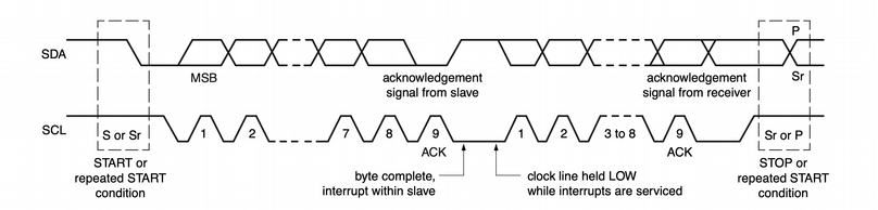
The master device sets the data signal low before the clock to signal the start condition. The address of our device is then sent on the bus, we get an interrupt request with the SR1 ADDR flag set. We clear that by reading SR1 and SR2. The interface sends an acknowledge pulse. The master sends data bytes. We read each byte (and thus clear the status). The master sends a stop condition. We clear that with an SR1 read, and a write to CR1, setting the state back into the ready to acknowledge state.
Each byte we receive, we write directly to our array of leds. This is fairly simple, so we can get away with running it inside our interrupt handler.
fn output_leds(leds: &mut [Pxx<Output<PushPull>>; 8], value: u8) {
    for (i, led) in leds.iter_mut().enumerate() {
        if (value >> i) & 1 > 0 {
            led.set_high().unwrap();
        } else {
            led.set_low().unwrap();
        }
    }
}
Here we run through our LEDs, shift and mask test our value to turn on the LEDs corresponding to the 1s in our input.
That's everything we need for a basic I²C 8-bit display. If you are building this yourself, see the led-test for an example without interrupts or I²C that you can use to make sure everything is connected correctly and everything lights up as it should.
We are going to use an Arduino as our example host device.
#include <Wire.h>

byte the_count;

void setup() {
  Wire.begin();
  the_count = 0;
}

void loop() {
  Wire.beginTransmission(0x33);
  Wire.write(the_count);
  Wire.endTransmission();
  the_count++;
  delay(80);
}
We'll use the Wire library to send a count, making each byte a separate transaction.
Let's give it a try.
What's Next
You can find the code here. Feel free to add a GitHub issue if you run into problems or have questions about making something similar.
See the next post for the 7-segment display where I add a few new features.
For me, I might take a look at adding I²C slave support to the libraries. I also will probably port this to another chip. With the current component shortage, everything is hard to find, but I suspect even once we get rolling again, we'll move on to more capable chips at this same price. So check back for that if you have an STM32F4xx based device.